UWK III Fan Convectors

  1. Homepage
  2. Products
  3. Fan coils
  4. UWK III Fan Convectors

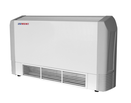
The fan convector is intended for the heating or cooling and ventilation of the interior of premises requiring more than two exchanges per hour. It mainly concerns the premises of the public service buildings, such as: offices, shops, computer rooms and other spaces requiring a periodical or continuous supply of fresh air.

PRODUCT DESCRIPTION

The basic subassemblies of the convector include:

  • structure made of galvanised steel with aluminium elements and powder-coated housing;
  • copper and aluminium fin heat exchanger intended for the heating or cooling as 2- or 4-pipe version with supply connected from below or from the wall;
  • drain tray for condensate,
  • 3x1kW electrical heater intended for the air additional heating in transitional periods;
  • fan with cross air flow;
  • mixing chamber built in the unit equipped with damper for control of fresh and circulating air share ratio (max. 50:50%) by adjustable hand lever;
  • air filter – class G2 or mesh;
  • temperature controller RAB3 – installation requires additional cable 7x1mm2;
  • heater valve Dn 15 with thermal servomotor installed in supply line of heat exchanger (system 2R – 1 pc. – system 4R – 2 pcs.) ,
  • power cable with grounded plug,
  • fresh air connection terminal.

Additional equipment includes:

  • air intake;

WORKING CONDITIONS

The low and intermediate speeds of the fan are foreseen for the continuous operation of the convector. The convector is intended for the operation in two positions: vertical (by the wall) and horizontal (suspended to the ceiling).
In the transitional periods in case of the lack of the hot water supply the heating function is taken over by the electrical heaters. When the medium with the temperature exceeding 50OC appears, the electrical heaters are switched off.
In both cases the fresh air supply is controlled by the damper located in the mixing chamber from 0 to 50% of the total air amount. The remaining air amount is taken from the room. For both operation positions the mixing chamber allows the air intake to be installed from below or behind the unit which ensures the use of various systems of fresh air supply. In order to install the air intake, the plug element must be removed from the mounting hole and replaced with the fresh air connection terminal, delivered together with the unit.
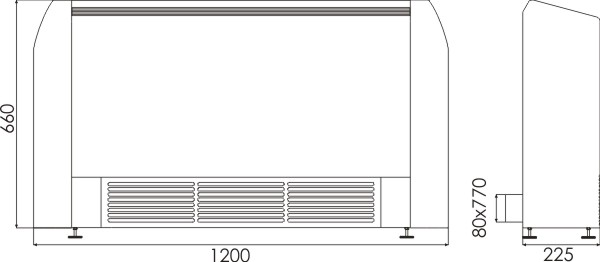
Technical data

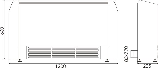
  • Dimensions

    Type UWK-W-2
    Fan power [W] 60
    Fan current [A] 0,29
    Revolutions [obr./min] 1340
    Air capacity [m3/h] 600 425 250
    Water parameters [OC] Inflow air temp. [OC] Thermal power [kW], and resistance of water flow [kPa]
    kW kPa kW kPa kW kPa
    90/70 0 12,5 9,0 9,8 5,6 6,5 2,5
    10 10,7 6,7 8,3 4,1 5,5 2,0
    20 8,6 4,6 6,9 3,0 4,6 1,3
    80/60 0 10,8 7,0 8,5 4,2 5,7 2,0
    10 9,0 4,8 7,0 3,0 4,7 1,3
    20 7,2 3,0 5,7 2,0 3,8 1,0
    70/50 0 9,0 5,0 7,2 3,0 4,8 1,4
    10 7,4 3,2 5.8 2,1 4,0 1,2
    20 5,7 2,0 4,5 1,2 3,0 1,0
    60/40 0 7,5 3,3 5,9 2,0 4,0 1,0
    10 5,7 2,0 4,5 1,5 3,1 0,9
    20 4,1 1,0 3,2 1,0 2,3 0,8
    Water parameters [OC] Inflow air temp. [OC] Thermal power [kW], and resistance of water flow [kPa]
    kW kPa kW kPa kW kPa
    5/10 28 3,5 24 2,5 18 1,8 10
    26 2,8 21 2,2 15 1,5 9
    24 2,3 15 1,8 9 1,2 5
    6/12 28 2,8 22 2,3 16 1,6 8
    26 2,3 16 2,0 13 1,3 6
    24 1,9 11 1,6 8 1,0 4

    Convector weight and noise level

      Air capacity [m3/h] 600 425 250
    Operation noise level [dB(A)]** 50 41 30
    Weight [kg] 44
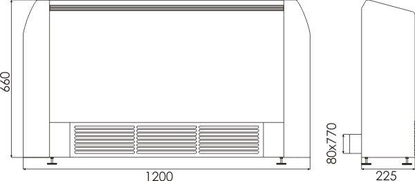
  • Dimensions

    Type UWK-W-4
    Fan power [W] 60
    Fan current [A] 0,29
    Revolutions [obr./min] 1340
    Air capacity [m3/h] 600 425 250
    Water parameters [OC] Inflow air temp. [OC] Thermal power [kW], and resistance of water flow [kPa]
    kW kPa kW kPa kW kPa
    90/70 0 5,0 1,5 4,1 1,1 3,1 1,0
    10 4,2 1,2 3,5 1,0 2,6 0,9
    20 3,5 1,0 2,8 0,9 2,2 0,8
    80/60 0 4,2 1,4 3,5 1,0 2,6 0,9
    10 3,5 1,2 2,9 0,9 2,2 0,8
    20 2,8 1,0 2,3 0,7 1,7 0,7
    70/50 0 3,5 1,2 2,9 1,0 2,2 0,8
    10 2,8 1,1 2,3 0,8 1,7 0,7
    20 2,1 1,0 1,8 0,6 1,3 0,6
    60/40 0 2,8 1,0 2,3 0,8 1,8 0,7
    10 2,1 1,0 1,8 0,6 1,3 0,6
    20 1,5 1,0 1,2 0,5 1,0 0,5
    Water parameters [OC] Inflow air temp. [OC] Thermal power [kW], and resistance of water flow [kPa]
    kW kPa kW kPa kW kPa
    5/10 28 2,9 29 2,3 19 1,7 11
    26 2,4 21 2,0 15 1,4 8
    24 2,0 15 1,6 10 1,1 5
    6/12 28 2,5 11 1,9 8 1,4 5
    26 2,0 8 1,5 5 1,1 3
    24 1,6 5 1,2 4 0,8 2
    7/14 28 2,0 7 1,7

    5

    1,2 3
    26 1,6 6 1,3 4 1,0 2
    24 1,3 4 1,0 3 0,7 1
    Convector weight and noise level
     Air capacity [m3/h] 600 425 250
    Operation noise level [dB(A)]** 50 41 30
    Weight [kg] 44
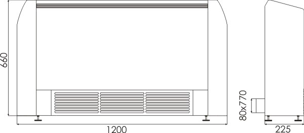
  • Dimensions

    Type UWK-E
    Fan power [W] 60
    Fan current [A] 0,29
    Revolutions [obr./min] 1340
    Air capacity [m3/h] 600 425 250

    Thermal power of electric heaters

    Thermal power [kW] 3 2 1

    Convector weight and noise level

    Operation noise level [dB(A)]** 50 41 30
    Weight [kg] 43
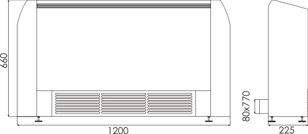
  • Dimensions

    Type UWK-E+W-4
    Fan power [W] 60
    Fan current [A] 0,29
    Revolutions [obr./min] 1340
    Air capacity [m3/h] 600 425 250
    Water parameters [OC] Inflow air temp. [OC] Thermal power [kW], and resistance of water flow [kPa]
    kW kPa kW kPa kW kPa
    90/70 0 5,0 1,5 4,1 1,1 3,1 1,0
    10 4,2 1,2 3,5 1,0 2,6 0,9
    20 3,5 1,0 2,8 0,9 2,2 0,8
    80/60 0 4,2 1,4 3,5 1,0 2,6 0,9
    10 3,5 1,2 2,9 0,9 2,2 0,8
    20 2,8 1,0 2,3 0,7 1,7 0,7
    70/50 0 3,5 1,2 2,9 1,0 2,2 0,8
    10 2,8 1,1 2,3 0,8 1,7 0,7
    20 2,1 1,0 1,8 0,6 1,3 0,6
    60/40 0 2,8 1,0 2,3 0,8 1,8 0,7
    10 2,1 1,0 1,8 0,6 1,3 0,6
    20 1,5 1,0 1,2 0,5 1,0 0,5
    Water parameters [OC] Inflow air temp. [OC] Thermal power [kW], and resistance of water flow [kPa]
    kW kPa kW kPa kW kPa
    5/10 28 2,9 29 2,3 19 1,7 11
    26 2,4 21 2,0 15 1,4 8
    24 2,0 15 1,6 10 1,1 5
    6/12 28 2,5 11 1,9 8 1,4 5
    26 2,0 8 1,5 5 1,1 3
    24 1,6 5 1,2 4 0,8 2
    7/14 28 2,0 7 1,7

    5

    1,2 3
    26 1,6 6 1,3 4 1,0 2
    24 1,3 4 1,0 3 0,7 1
    Thermal power of electric heaters
    Air capacity [m3/h]  600  425  250
    Thermal power [kW]  3  2  1
    Convector weight and noise level
    Operation noise level [dB(A)]** 50 41 30
    Weight [kg] 48
  • Dimensions

    Type UWK-E+W-2
    Fan power [W] 60
    Fan current [A] 0,29
    Revolutions [obr./min] 1340
    Air capacity [m3/h] 600 425 250
    Water parameters [OC] Inflow air temp. [OC] Thermal power [kW], and resistance of water flow [kPa]
    kW kPa kW kPa kW kPa
    90/70 0 12,5 9,0 9,8 5,6 6,5 2,5
    10 10,7 6,7 8,3 4,1 5,5 2,0
    20 8,6 4,6 6,9 3,0 4,6 1,3
    80/60 0 10,8 7,0 8,5 4,2 5,7 2,0
    10 9,0 4,8 7,0 3,0 4,7 1,3
    20 7,2 3,0 5,7 2,0 3,8 1,0
    70/50 0 9,0 5,0 7,2 3,0 4,8 1,4
    10 7,4 3,2 5.8 2,1 4,0 1,2
    20 5,7 2,0 4,5 1,2 3,0 1,0
    60/40 0 7,5 3,3 5,9 2,0 4,0 1,0
    10 5,7 2,0 4,5 1,5 3,1 0,9
    20 4,1 1,0 3,2 1,0 2,3 0,8
    Parametry wody [OC] Temp. powietrza napływ. [OC] Moc chłodnicza [kW], oraz opory przepływu wody [kPa]
    kW kPa kW kPa kW kPa
    5/10 28 3,5 24 2,5 18 1,8 10
    26 2,8 21 2,2 15 1,5 9
    24 2,3 15 1,8 9 1,2 5
    6/12 28 2,8 22 2,3 16 1,6 8
    26 2,3 16 2,0 13 1,3 6
    24 1,9 11 1,6 8 1,0 4
    Thermal power of electric heaters
    Air capacity [m3/h]  600  425  250
    Thermal power [kW]  3  2  1
    Convector weight and noise level
    Operation noise level [dB(A)]** 50 41 30
    Weight [kg] 48